
Summary of Testing:
The intentions of the tests were to ensure that the RC car would perform well in a drag race, slalom race, and Baja race. The drag race was on concrete, and the team expected that the car would make it to the end of the 25 foot drag strip in 4 seconds. To do this the engineer responsible for steering had to ensure that the car could hold a straight line at high acceleration. The slalom race required that the car could effectively turn between a series of cones, for this race the engineer tested the maximum steering angle to ensure that the car could actually make it through the cones. For the Baja race the car would need to accelerate quickly and turn sharply just as in the previously mentioned races; However, this race would also include three jumps where the RC car would likely experience a fall from 2 feet.
The drag race requires that the car is able to hold a straight line at high accelerations. To ensure this the engineer tested the slop in the steering system. If the slop in the steering system was less than 3 degree then the car passes the test. If the car did not pass the test then the engineer would have modified the system until the car passed. The car was required to have a minimum turn angle of 50 degree for the slalom race, the car was predicted to be able to turn at an angle of 55 degree. To test this the engineers planned to measure the radius of a 180 degree turn to determine the turning angle. The car was predicted to experience frequent drops from 2 feet during the Baja race, therefore the engineer required that the shocks would not compress more than 3” when falling from this height. To test this the engineer used a slow motion camera and a ruler to see and record how much the shocks compressed after a drop.
The testing for each requirement outlined in section 1d-1-18 of the engineering report involved specific procedures tailored to each criterion. Shock eyelet pins were tested on an Instron machine with a 40 lb double shear force to ensure they didn't yield. Any deformation post-testing was observed to verify the results. The car turn angle was determined by measuring the radius of a 180-degree turn. The deflection of the lower control arm under a 20 lb load was measured using the Instron machine. Trailing arms and rear axle actuation were tested by measuring their movement range. Shock compression after a drop was assessed using a slow-motion camera. Deflection limits for various components under different loads were tested using fixed rulers and slow-motion recording. Tests were conducted in controlled environments, mainly on flat ground in well-lit areas such as the Hogue Fluke Lab. Tools like the Instron machine, measuring tape, slow-motion cameras, and 3D printed jigs were utilized for accuracy and consistency.
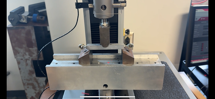
Figure 15 rear trailing arm deflection test
The test shown above is the deflection test of the rear trailing arm. This test was done to determine the deflection of the rear trailing arm under an 8.5-pound load. Under 8.5 pounds the trailing arm did not deflect enough to give significant data, so the engineer put more force on the beam and collected data up to 0.0625" of deflection.

Figure 16 Drop test
The image shown above is the drop test done to determine the max compression of each shock after a 2 foot drop. As seen, each shock bottomed out and this test was a fail. To remedy the issue the engineer ordered stiffer springs for the shocks.

The image to the right is a simple graphic that shows what a 3 point bend test looks like. This test was performed on the rear trailing arms as well as the control arms.
Figure 17 three point bend diagram

Figure 18 Articulation of suspension
The above image is of an informal test of the suspension articulation. The engineer estimates that the articulation of the highest wheel in this image was about eight inches.

Figure 19 Baja Competiton results
As shown above the engineers achieved 2nd place overall in the device competition and tied for 1st place in the Baja Rally competition. This competition was the ultimate real world test of the entire device and put every component to the test.
Figure 20 Drop test video
Above is the drop test video showing the compression of the shocks after a two foot drop.
Requirements
-
Shock eyelet pins were required to not yield under 40 lbs. of shear force in double shear.
-
Car needed to have a 50-degree minimum turn angle.
-
Lower control arm had to deflect less than 0.0625” under 20lb load.
-
Trailing arms and rear axle had to actuate at least one inch up or down.
-
Shock tower had to weigh less than 4oz.
-
Needed a minimum of 3” of ground clearance at static ride height.
-
Needed to not compress shocks more than 3” after a 2’ drop.
-
Arm of shock tower had not deflect more than 0.0625” under 8 pound total static load (2 pound load at each tire).
-
Tie rods and control arms needed to not deflect more than 0.0625” during a front-end impact at 5 mph.
-
Trailing arms had to deflect less than 0.0625” under a 8.5 pound point load at the center of the long axis.
-
Tie-Rods had to resist buckling from a 20lb axial load.
-
The shear stress on the control arm/bulkhead bolt had to not exceed 42,500psi.
-
Bearing stress on control arm mounting hole had to be less than 4351psi.
-
Shear on caster block pin had to be less than 42,500psi.
-
Trailing arms had to be able to resist buckling under 100lb axial load.
-
Upper long arm had to be able to resist buckling under 40lb axial load.
-
Steering rack connecting bar had to resist buckling under 25kgf load
-
Deflection of rear shock tower arm had to be less than 0.0625” under 24lbf load
The engineer focused his testing efforts on the three tests listed in bold (3,7,10)