
Summary of Analysis:
In section 2e of the proposal the engineer described the scope of testing and evaluation for components and systems of the RC car. Testing ranged from tensile testing of tie rods to impact tests for the entire RC car assembly. Other testing involved drop tests, driving tests, and static load tests. Analysis was done prior to testing for each component, the analysis involved application of statics, mechanics of materials, dynamics, and kinematics. Each analysis resulted in a design parameter that governed the final design. The resulting design parameters were usually a size parameter to ensure the durability of components but sometimes the resulting parameter was related to weight or material properties.
Analysis 1
Shear and bearing stress analysis on control arm and mounting bolt:

This analysis was used to determine the minimum size of the mounting control arm mounting bolt and the minimum width of the control arm mounting section. The shear stress acting on the mounting bolt was assumed to be 20lbs acting on the bolt in double shear. The components were required to be within a safety factor of 2 from the yield points of the materials The maximum shear stress of a steel bolt was determined to be 42,500psi; Assuming an 1/8" bolt the maximum shear stress seen by the component was 203.7psi. This determines that an 1/8" bolt is appropriate for this application. Then the maximum bearing stress on the control arm and bulk head was found to be 4351psi. The bearing stress is found by using Force/Area, where the area is the cross section where the bolt makes contact with the part. The maximum bearing stress seen by the bulkhead assuming 0.3125" wide was 256psi, the maximum bearing stress seen by the control arm assuming 0.1875" wide was 853psi. Since both bearing stresses are less than the allowable stress, the assumed width dimension are found to be suitable.
Figure 4: Stress analysis of control arm mounting point
Analysis 2
Trailing Arm Deflection:

Trailing arm deflection was required to be less than 0.0625" when a 8.5lb load is applied to the center of the beam. The beam was 3" long and made of 6061 aluminum. This analysis was done by assuming that the cross section of the beam was 0.5" tall and 0.25" wide. Using the beam deflection equation found in Mott Appendix 14-1(a) the deflection is found to be 0.00018". This deflection is well within the requirement specified and shows that the assumed cross section is an appropriate size for this application.
Figure 5: Trailing arm deflection
Analysis 3 Page 1
Analysis 3 Page 2

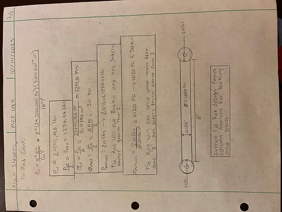
Figure 6: Tie-Rod buckling analysis page 1
Figure 7: Tie-Rod buckling analysis page 2
Tie-Rod Buckling Analysis:
The Tie-Rod buckling analysis was done to determine if the chosen rod size was appropriate. The rod was to be made out of low carbon steel in accordance with ASTM-A108. The chosen dimensions for the rod were 0.158" in diameter and 6" long. The rod was required to be within a safety factor of 2 from the critical buckling load when a 20lb axial load was applied. The first step of this analysis was to determine whether the beam was long or short. To do this the slenderness ratio was compared to the transitional slenderness ration. The beam was determined to be a long beam and therefore the Euler equation applied. After applying the Euler equation the critical buckling load was determined to be 2441.96lbs. Once the safety factor was applied the max axial load was found to be 1220.98lbs. Finally a stress check was done to ensure that the 20lb load didn't exceed the calculated max stress of 30,000psi. The actual stress was 1020psi; Since both the axial load and stress were within the calculated limits, the chosen dimensions for the component was found to be suitable for this application.